Diaphragm Pumps for Gas
How does a Diaphragm Pump work?
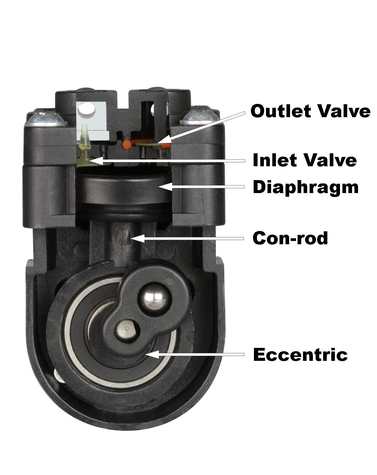
A diaphragm pump works through a principle of a moving diaphragm within a pumping chamber causing expansion and compression of the air / gas inside it. The diaphragm is moved by a con-rod which is attached to a rotating eccentric driven by the shaft of a motor. The distance between the lower and upper position of the diaphragm is known as the stoke of the pump. A diaphragm pump has two sets of valves which allow air / gas to flow in one direction only. One valve is on the inlet allowing air to enter the chamber of the diaphragm pump and a second valve is on the outlet allowing air to exit the pump chamber. As the diaphragm moves down, air enters the pump chamber. As the diaphragm moves up, the air is compressed and exits the pump. A typical diaphragm pump from Boxer has a stroke of 1.0 to 6.0 mm and a compression ratio of 4 to 1, which theoretically provides a maximum vacuum of 75% and maximum pressures above 2 bar.
The so-called ‘wetted parts’ of a diaphragm pump are the parts which come into contact with the air / gas. This term is taken from a liquid diaphragm pump and is literally the internal parts which would become wet when pumping a liquid. These parts are important for a diaphragm pump since chemical combability is vital for reliable operation and longevity. The typical wetted parts of a diaphragm pump include the plastic pump body / ports and elastomers which include gaskets / O-rings, valves and the diaphragm itself. The plastic parts in a typical diaphragm pump from Boxer are made from PPS (polyphenylene sulphide) and the choice of elastomers is typically silicone, EPDM, nitrile, viton (FKM) of FFKM. The application details such as media compatibility and lifetime requirements will determine the choice of material selected for a particular diaphragm pump configuration.
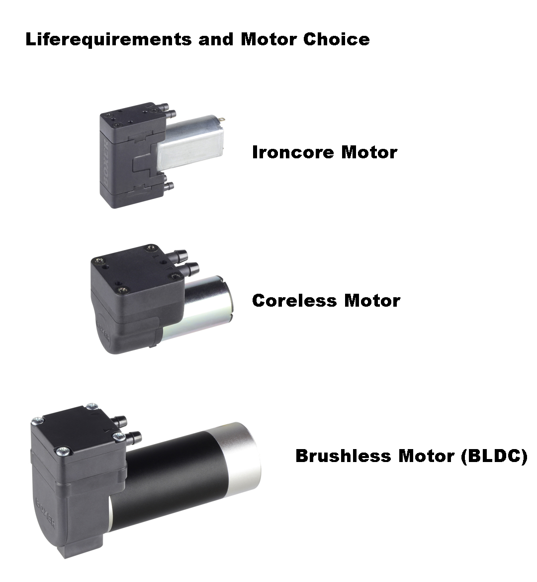
Life Requirements and Pulsation
Matching the life requirements to a particular application is important when selecting the configuration of a diaphragm pump. Applications range from systems which run 24 hours a day / 7 days a week to system where the diaphragm pump runs for just a few seconds per day. The cost of a diaphragm pump is very sensitive to the choice of motor, since this is normally the most expensive component used in the pump’s construction. Lowest cost (and the associated lowest motor life) is a configuration of diaphragm pump which uses an iron core motor. Mid-range cost and life would be a diaphragm pump driven by a coreless motor. And finally, the upper end of cost and life would be a diaphragm pump driven by brushless DC (BLDC) motor. As mentioned above, the elastomers of a diaphragm pump should also be selected depending on the application’s life requirements.
If physical space allows, for applications requiring long life the designer should also consider selecting a larger diaphragm pump and running it at lower speed. For example, a diaphragm pump with 12V DC motor can generally be run at 6 V providing approximately half the flow. In comparison to a smaller pump running at full / nominal speed, the larger diaphragm pump will not only benefit from fewer strokes for a given flow, but also running temperatures are reduced which provides advantages for both the motor and elastomers.
Due to the nature of operation, a diaphragm pump supplies pulses of air rather than a linear flow. Consider the outlet air flow as the diaphragm pump produces a complete pumping cycle, starting with the diaphragm in the upper position. As the diaphragm moves downwards air / gas enters the pump chamber via the inlet port and inlet valve. During this time the outlet valve is closed and hence the diaphragm does not produce any air flow on the outlet. The pump chamber of the diaphragm pump has its maximum volume when the diaphragm is in its lower position. During the second half of the rotation the air / gas inside the chamber of the diaphragm pump is compressed. Only when the pressure inside the chamber is larger than the pressure of system to which it is connected does the outlet valve open. From this point onwards until the diaphragm is in the upper position does the diaphragm pump produce flow on the outlet.
In some applications which use a diaphragm pump pulsation is not desirable. For example, such an air flow can cause significant errors of gas sensors measure the concentration of the gas. In such applications gases pulsation from a diaphragm pump can be minimised by using a double headed pump which are 180° out of phase. For each complete cycle of rotation, the diaphragm pump produces 2 phases of air flow when the outputs are connected in parallel. This is a commonly used configuration a of diaphragm pump for pulsation sensitive applications.