Peristaltic Pumps for Liquid

How does a Peristaltic Pump Work?
A peristaltic pump works through the principle of multiple rollers compressing a tube as they rotate around a partial circumference inside a pump body. Between the rollers a chamber of liquid is trapped, and it is transferred from the inlet side to the outlet side of the peristaltic pump. The rollers and roller positions are designed in such a way that the roller on the inlet side occludes the tube before the roller on the outlet side moves away from the tube on the outlet side. Peristalsis is the medical term for muscular contractions of the digestive track in a wavelike motion. The peristaltic pump replicates this motion and is the origin of its name.
A peristaltic pump has the unique feature that the media comes into contact with only the tube. With alternative pump technologies the so called ‘wetted parts’ includes valves, pump bodies, diaphragms etc. These parts are difficult to clean in comparison to a peristaltic pump, which requires only flushing with a neutral media or replacement of the tube. Additionally, chemical compatibility of a peristaltic pump is a matter of checking against the tube material rather than a longer list of wetted parts.
The peristaltic pump tube is critical in determining the pumps characteristics. Due to the principle of how a peristaltic pump operates, the tube must have sufficient elasticity over a long period of time to open once the roller moves away. A peristaltic pump running at 300 rpm with 3 rollers will compress the tube over 50 million times in 1000 hours of operation. Special tubing has been developed for peristaltic pumps and is generally based around thermoplastic elastomers. Additionally, the tube must be correctly sized for a specific peristaltic pump. The wall thickness of the tube is critical since the internal dimensions of the pump are designed to occlude the tube. So, for example if a peristaltic pump is designed for 1.6 mm wall tubing, a 1.0 mm wall tubing will not occlude in the same pump and a pumping motion will not occur. Also due to physical limitation of size and motor torque, the tubing size should always stay within the internal diameter range specified for a particular peristaltic pump series.
Choice of Motors, Exchange of Tubing, Pulsation
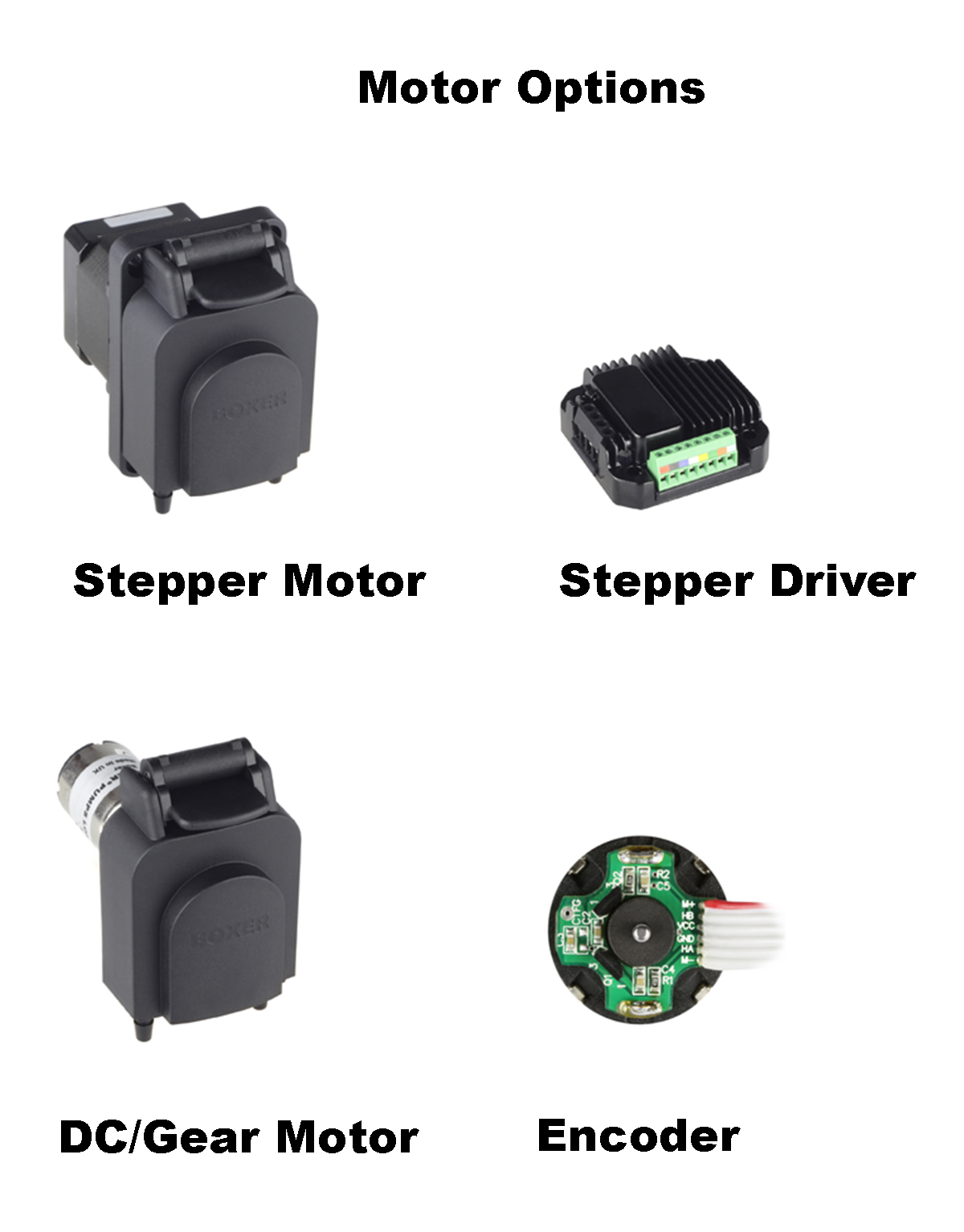
In many applications the flow of a peristaltic pump is controlled accurately by knowing the speed at which the rollers pass over the tube. The roller assembly is either driven directly from the motor shaft or via a gearbox between the motor and peristaltic pump head. For the greatest accuracy and controllability, a peristaltic pump is most often driven directly by a stepper motor. Such motors allow the user to precisely control the peristaltic pump speed (typically between 0 and 500 rpm) and direction. These motors are generally a 2-phase bipolar construction and require a separate external driver to generate the correct sequencing signal to the motor coils. The alternative is to drive the peristaltic pump via a DC motor with gearbox. They have the advantage of not requiring a separate driver, however the minimum speed is limited to approximately 50% of the peristaltic pump’s nominal or full speed. Both DC motor and some stepper motor peristaltic pumps are available with an encoder to provide a signal output providing speed (and therefore) flow information.
In many applications the tubing
inside the peristaltic pump will be changed frequently over the life of
the pump. Design vary from a cassette style whereby the peristaltic pump
is opened, and a new tube set or length of continuous tube is replaced,
or a flip-top style whereby the pump is partially opened via a lever
and new piece of tube is laid through the guides and rollers.
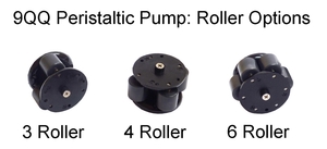
The flow of a peristaltic is said to pulsate. This is actually an interruption, or partial interruption, of flow as the roller moves away from the tube at the outlet. During this part of rotation the flow inside the peristaltic pump is filling the tube as it opens rather than producing flow at the output. The level of pulsation is determined by the geometry of the peristaltic pump’s design. More rollers inside the head decrease the level of pulsation, which improves peristaltic pump accuracy for low volume dosing, however the general flow of the pump will also decrease since the additional rollers pinching the tube reduce the internal pumping volume inside the tube.
Peristaltic Pump - FAQ
The choice of tubing to be used for a peristatic pump is critical to meet the needs of both the peristaltic pump itself and the application. 3 factors of the most important factors are discussed below:
1 Correctly Dimensioned
An
obvious starting point is that the tube needs to be correctly
dimensioned for a particular peristaltic pump. As the rollers move over
the tube they compress and occlude the tube. The peristaltic pump must
therefore be designed so that the gap between the rollers and pump body
is less than twice the wall thickness of the tube – otherwise occlusion
will not occur, and the pump will be very ineffective. Therefore, a
peristaltic pump is designed for a particular wall thickness of a tube.
Within the Boxer range, this is either 1.0 mm, 1.6 mm or 2.4 mm.
Secondly, a peristaltic pump is designed to operate within a range of internal diameters of a tube. This data is provided in the datasheets and it is not recommended to operate the peristaltic pump outside this range. For example, the 9QQ peristaltic pump is designed for internal diameter tube of 0.5 mm to 3.5 mm and always with a wall thickness of 1.0 mm.
2 Elasticity / Fatigue
As
described in the introduction, a peristaltic pump operates by
compressing a tube around a partial circumference of the pump’s body. As
the rollers pass over the tube it is vital for the function of the
peristaltic pump that the tube re-opens once the rollers move away. This
is determined by the elasticity of the tube. Consider a peristaltic
pump running at 300 rpm with 4 rollers for 6 weeks continuously. During
this time, each part of the tube is compressed over 72 million times. If
not designed for operation in a peristaltic pump, a tube will suffer
fatigue as elasticity is lost, the tube will flatten and flow
performance reduces. For this reason, special thermoplastic elastomers
have been developed as peristaltic pump tubing which remain highly
elastic over a long operation life.
3 Chemical Compatibility
The
final critical element to the choice of tube to be used in a
peristaltic pump is chemical compatibility. Guides are available for
different peristaltic pump tubes against a long list of media; however,
it is almost always recommended to perform a dynamic test with the tube
installed in the peristaltic pump under the regular conditions of the
application.
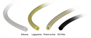
Silicone: generally inert giving excellent chemical compatibility, low durometer (reduces load on peristaltic pump), low cost, however very limited life.
Lagoprene: a good general-purpose thermoplastic elastomer, good chemical compatibility, long life
Pharm-a-line: similar to lagoprene offering with good general-purpose tube with good chemical compatibility and long life, however additionally with biocompatibility to USP Class VI and FDA to 21CFR177.2600.
ED-Plex: a thermoplastic elastomer with chemical compatibility advantages over Lagoprene and Pharm-a-line for aqueous fluids, acids, bases and some oils / hydrocarbons.
The flow of a peristaltic pump is interrupted as the rollers engage and disengage from the tube. For example, considering the outlet flow, as the roller moves away from the tube it expands back from flat to its original shape. During this expansion the flow from behind the roller is partly used to fill the void. Hence the flow from the peristaltic pump decreases momentarily during this part of the rotation. The level of decrease depends primarily on the angle of which the rollers break away from the tube, roller diameter and outlet pressure. In some cases, the flow will momentarily reverse.
If the peristaltic pump is assembled with more rollers the frequency of the 'flow interruption' is increased giving the effect of reduced pulsation. In addition, since more rollers generally means less volume between rollers, the expansion of the tube as the rollers move away is reduced in proportion to the volume available for flow.
More rollers are however only recommended where needed since tube wear is significantly increased.
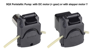
Generally, a peristaltic pump from Boxer is available driven with either a DC motor (+ gear) or stepper motor. A DC motor peristaltic pump has a planetary gear between the motor and peristaltic pump head to reduce the motor speed (typically above 6000 rpm) to between 33 and 520 rpm. A stepper motor driven peristaltic pump is driven directly from the motor and can be run from 0 to above 500 rpm. So which configuration of peristaltic pump is best suited to the application? This can be determined by considering the advantages of both drives:
Peristaltic pump with DC motor + gear:
+ simple control via DC supply (no external driver needed)
+ smaller size
+ lower power consumption
+ more economic
+ less prone to stalling
+ less prone to overheating
+ higher resolution encoder available to provide accurate speed feedback
Peristaltic pump with stepper motor:
+
full range of speed available, from 0 to max rpm, typically above 500
rpm (DC motor + gear is limited to approx 50% on nominal speed)
+ controllable acceleration and declaration
+ higher accuracy doing
+ reversible with a control signal (DC requires reversed polarity of motor supply)
+ lower sound level (see FAQ on mechanical resonance)
+ long motor life, typically above 10,000 running hours (DC is typically 1000 to 4000 hours)
By far, the most common criteria for selecting a stepper motor driven
peristaltic pump is the flow range the application requires. If, for
example, an analyser specifies to control the flow from 10 ml / min to
150 ml / min, a stepper motor driven peristaltic pump in the clear
choice since a DC + gear driven peristaltic pump will only be able to
reduce the flow to approx 50% of nominal flow, so for this example this
is approx 75 ml / min to 150 ml / min.
The numbers are less significant, however importantly it should be understood that the torque is highest at low speeds and decreases with increasing speed. This means, regardless of tube size, tube material, media, suction or pressure height, a peristaltic pump can always be made to stall if the rpm or acceleration is too high.
So, what can be done to prevent a stepper motor driven peristaltic from stalling? The follow factors should be considered:
The tube is not suitable for a peristaltic pump or is the wrong size:
As
discussed in FAQ ‘What should be considered when selecting the tube for
a peristaltic pump?’ the tube should be suitable for a peristaltic
pump, have the correct wall thickness and be with the range of inner
diameters suitable for the peristaltic pump series.
The speed is too high:
The
most common cause of stalling is simply attempting to drive the
peristaltic pump too fast. It is always better to start at a slower
speed and increase to the desired speed.
The acceleration is too high:
Closely
related to the previous factor, moving from speed 1 to speed 2 should
be a transition over say 0.5 seconds rather than an instantaneously jump
in speed of the peristaltic pump.
The current limiter is too low:
Most
drivers have a current limiter which is used to reduce motor
temperature. This has the effect of reducing the available torque
available to the peristaltic pump head. When adjusting the current
limiter, attention should be made in keeping well above the stall point,
especially considering installing new tubing in the peristaltic pump.
The power supply cannot provide enough current:
A
stepper motor draws peaks of current rather than a constant current.
When running a peristaltic pump, an average current of say 1.0 amps may
be observed on the power supply but in reality, the current peaks are
much higher. If the power supply is not able to provide the high peaks
of current, then the peristaltic pump will stall at lower speeds. As a
general rule, match the power supply to the maximum driver rating.
The supply voltage is too low:
All
of the Boxer stepper motor driven peristaltic pump series are rated as
24 V. However, it is perfectly possible to run at a lower voltage
without damaging the motor. As would be expected, this does reduce the
maximum speed of the peristaltic pump before stalling occurs.
The tube is new:
The
most critical time for stalling of a peristaltic pump is when the tube
is new. Even after just 10 seconds or so of running the tube will soften
up. So, for example, if after experimenting with a peristaltic pump and
a piece of tube it is found that the maximum speed is 600 rpm, then a
new piece of tube is put in the pump, it will most likely stall. Maximum
speed of a peristaltic pump should therefore always be verified with
new and unused tubing.
Slowly closing the lid:
Most
peristaltic pump series from Boxer have a flip-top lid design. It is
therefore possibly to slowly close the lid of a peristaltic pump on a
new piece of tube whilst running to avoid stalling.
The maximum speed will vary for different tube sizes and materials:
The
load on a peristaltic pump will depends on both the size and material
of the tubing. Therefore, for example, a pump with an inner diameter
tube of 1.0 mm will be able to run faster than with a inner diameter
tube of 2.0 mm. Likewise a silicone tube will be able to run faster than
a Pharm-a-line tube with higher durometer / stiffness.
Viscosity and temperature of media:
The
media itself will also play an important role in determining the
maximum speed of a peristaltic pump. A high viscosity oil, for example,
will put a higher load on the peristaltic pump compared to water. This
will lower the stall speed. Similarly, a media at lower temperature will
increase the stiffness of the tube and reduce the maximum speed.
Peristaltic pumps rely on the elasticity of the tubing for successful operation. After the roller moves away the tube should open up fully and quickly. The response time of the tube is a significant factor in determining the flow rate and suction height. When the pump’s media is a viscous liquid the response time of the tube decreases and a higher vacuum level is required to pull the media into the peristaltic pump head.
The flow data on Boxer’s website is water at room temperature. As viscosity
increases, flow at constant speed will decrease. Water has viscosity of 1 mPa.s
(milli pascal seconds). Light oil has viscosity of 100 mPa.s. The upper limit
for a peristaltic pump is in the range of 5,000 to 10,000 mPa.s, which
corresponds to the consistency of syrup or liquid honey.
Compared to other technologies such as diaphragm pumps, peristaltic
pumps are actually very good at pumping viscous liquids, however attention
should be given to the following:
- Peristaltic pump flow will always decrease with increasing viscosity.
-
Slower rpms are recommended (to give the tube more time to open).
-
Use the highest tube wall thickness (increases restoring forces).
-
Use a large ID but not necessary the largest. A 6.4 mm ID with 2.4 mm wall will give better results than 8.0 mm ID with 2.4 mm wall.
- New tubing is better at pumping viscous liquids than run-in tube. So be sure your desired flow is also possible with a run-in tube (say after 25 hours).